
 Image 1 of 6
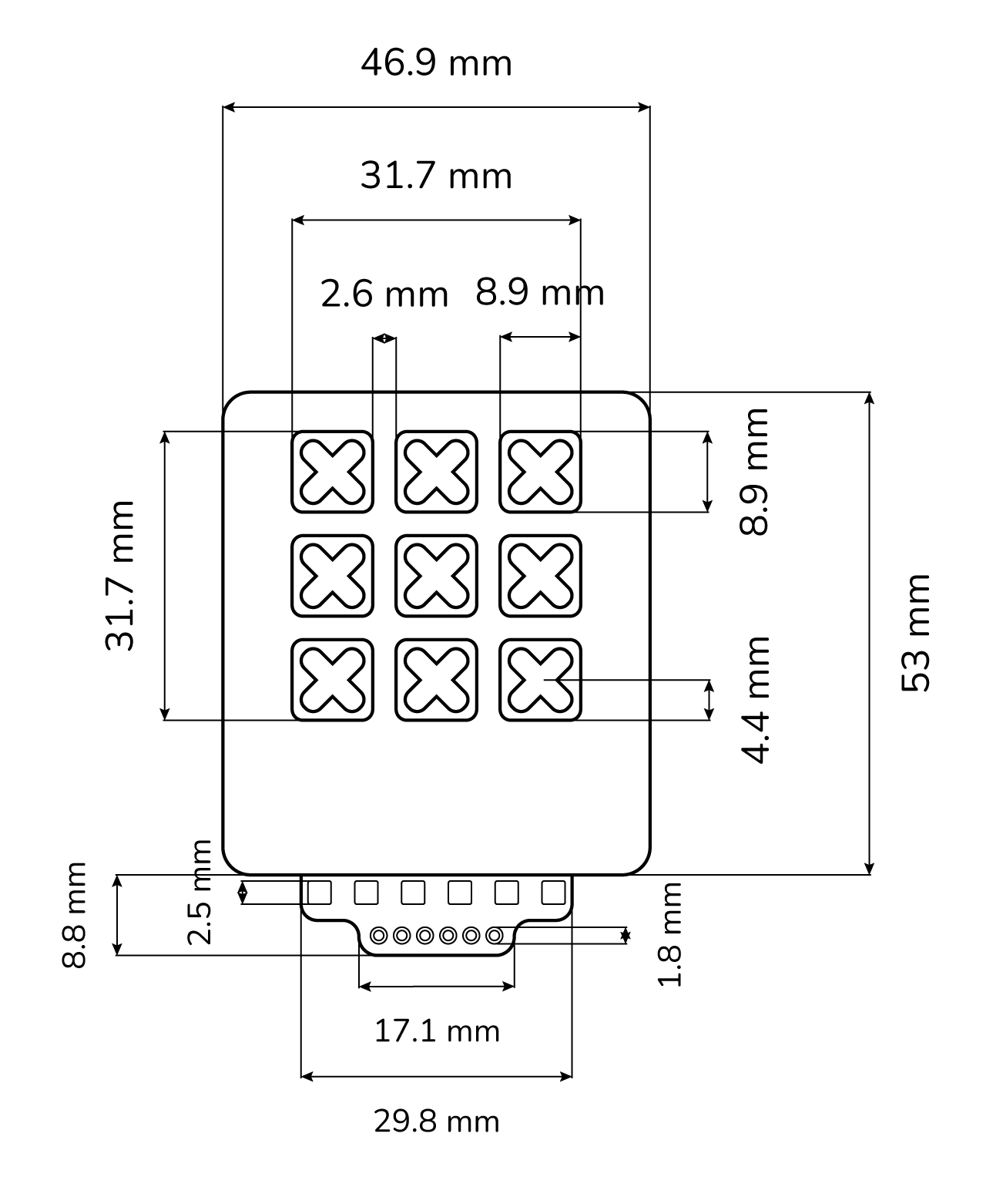 Image 2 of 6
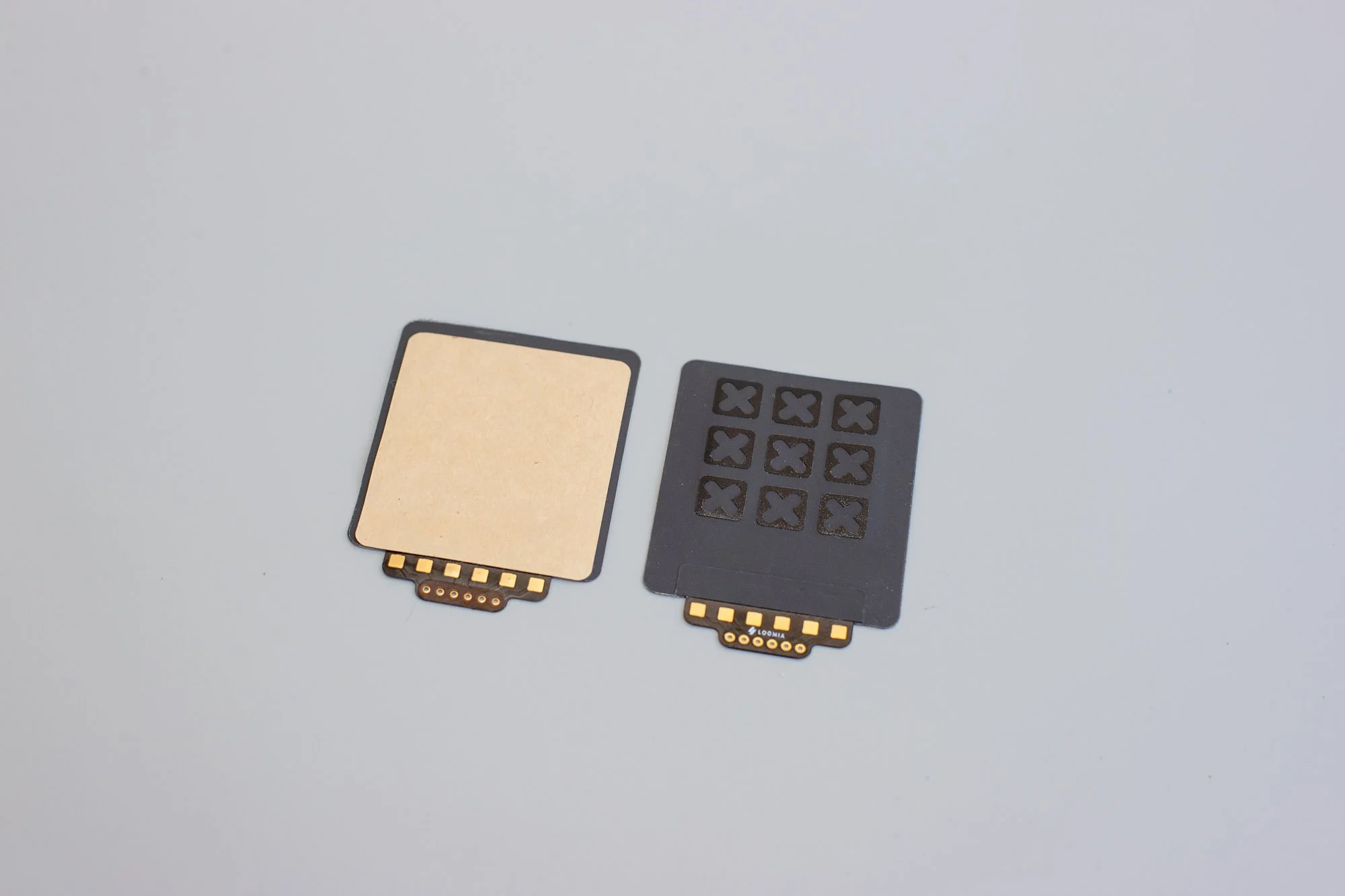 Image 3 of 6
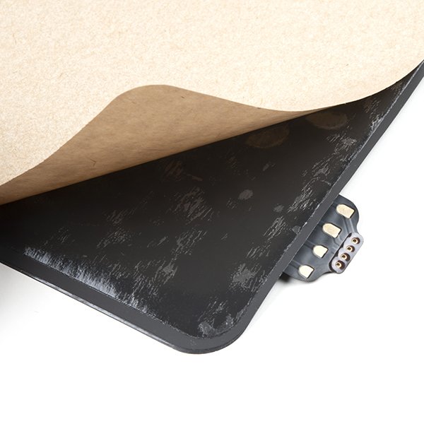 Image 4 of 6
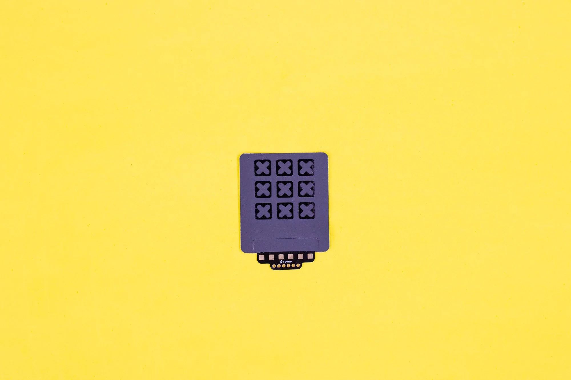 Image 5 of 6
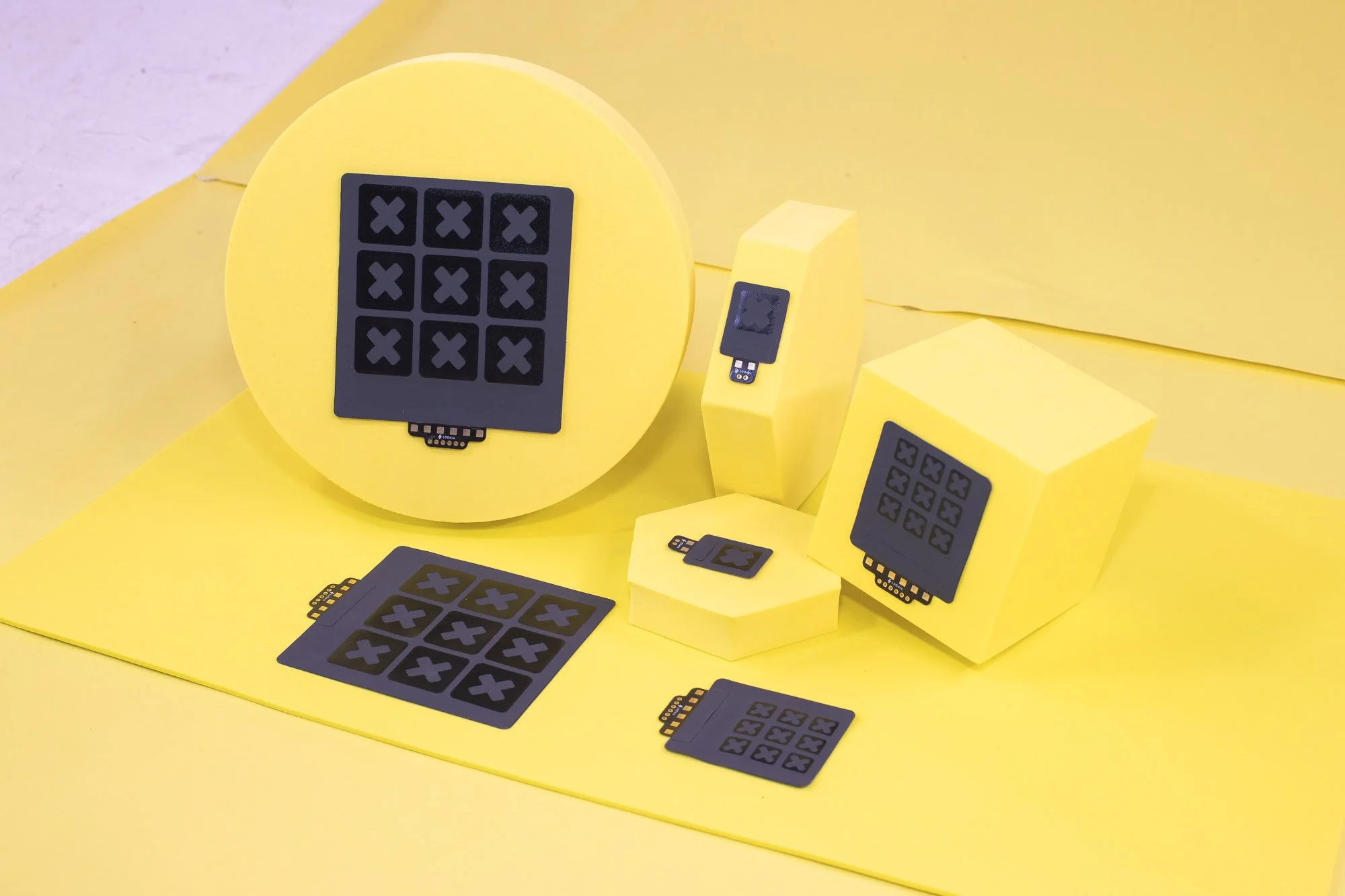 Image 6 of 6
Loomia Force Sensitive Resistor (FSR) Features Overview
The table below provides data on standard Loomia FSR performance:
Resistive Sensor Specifications
13.3% over 1 hour at 50 N
10,000+ cycles at 50 N
Avg 1% per cycle (10 cycles at 50 N)
Arduino + Python Scripts
8-week lead time required
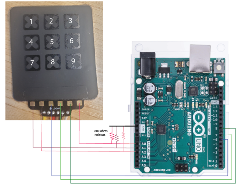
Arduino Code (serial monitor)
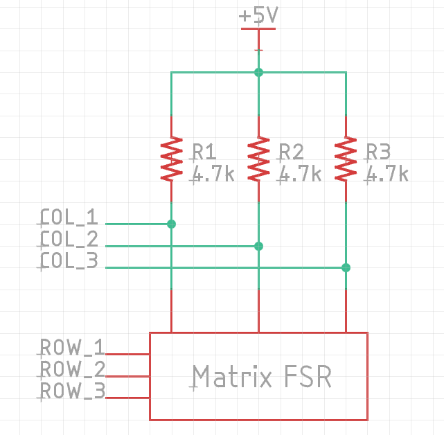
int colPins[3] = {6, 7, 8};     // Columns: GPIO outputs
int rowPins[3] = {A0, A1, A2};  // Rows: Analog inputs

const unsigned long samplingInterval = 100;  // Sampling every 30 s
unsigned long lastSampleTime = 0;
unsigned long startTime;

void setup() {
  Serial.begin(115200);

  for (int i = 0; i < 3; i++) {
    pinMode(colPins[i], OUTPUT);
    digitalWrite(colPins[i], LOW);
  }

  startTime = millis();
  lastSampleTime = 0;

  // CSV Header
  Serial.print("t");
  for (int r = 1; r <= 3; r++) {
    for (int c = 1; c <= 3; c++) {
      Serial.print(",R");
      Serial.print(r);
      Serial.print("C");
      Serial.print(c);
    }
  }
  Serial.println();

  // First sample at time = 0
  logSample(0);
}

void loop() {
  unsigned long currentTime = millis();

  if (currentTime - startTime >= lastSampleTime + samplingInterval) {
    lastSampleTime = currentTime - startTime;
    logSample(lastSampleTime);
  }
}

void logSample(unsigned long elapsedTime) {
  Serial.print("t_");
  Serial.print(elapsedTime);

  for (int row = 0; row < 3; row++) {
    for (int col = 0; col < 3; col++) {
      digitalWrite(colPins[col], HIGH);
      delayMicroseconds(50); // settle time
      int val = analogRead(rowPins[row]);
      digitalWrite(colPins[col], LOW);

      Serial.print(",R");
      Serial.print(row + 1);
      Serial.print("C");
      Serial.print(col + 1);
      Serial.print("_");
      Serial.print(val);
    }
  }

  Serial.println();
}
Arduino Pinout
Arduino Code for Visualizer
/* Loomia - 3x3 Mini Pressure Matrix v1.0.2
Written for Loomia Technologies
By David Choi, Copyright 2025
Created: 6/17/2025
Modified: 11/24/2025
Description:
- For use with resistive matrices (3x3) with data output formatted for the Loomia Pressure Matrix Visualizer.
- Note: This code doesn't swap X-Y inputs for symmetrical outputs since touch point crosstalk is inherent to the resistive matrix design and no other electronics are used.
Hardware:
- Arduino Uno or compatible MCU with 10 bit ADC inputs
- Loomia 3x3 Pressure Matrix (V2 prototype)
- 4.7k external pull ups on column pins
Matrix Layout: X = Column; Y = Row; Origin = (1,1)
(Top: Pad Location)
Y3 |_ (1,3) _|_ (2,3) _|_ (3,3) _|
Y2 |_ (1,2) _|_ (2,2) _|_ (3,2) _|
Y1 |_ (1,1) _|_ (2,1) _|_ (3,1) _|
X1 X2 X3
Data Output Order: (1,1), (2,1), (3,1), (1,2), (2,2), (3,2), (1,3), (2,3), (3,3)
Data Output Format (all values uint16_t): val11,val21,val31,val12,val22,val32,val13,val23,val33\n
Change Log:
v1.0.2:
- High-Z for rows not being scanned. Improves intercell crosstalk somewhat.
- Add 4.7kΩ external pullups on columns
- Changed pins to match straight wiring fixture
*/
#define X1 A1
#define X2 A2
#define X3 A3
#define Y1 A0
#define Y2 A5
#define Y3 A4
const int16_t MAX_VALUE = 1023; // Due to 10 bit ADC
const uint8_t MAX_ROWS = 3;
const uint8_t MAX_COLS = 3;
uint8_t cols[MAX_COLS] = { X1, X2, X3 };
uint8_t rows[MAX_ROWS] = { Y1, Y2, Y3 };
uint16_t dataMatrix[MAX_ROWS][MAX_COLS] = {};
void setup() {
// Initialize pins
for (int i = 0; i < MAX_COLS; i++) {
pinMode(cols[i], INPUT); // Use external pull ups on columns (4.7k)
}
for (int i = 0; i < MAX_ROWS; i++) {
pinMode(rows[i], INPUT); // Set to high-Z
}
Serial.begin(9600);
}
void loop() {
readCells();
printData();
delay(50);
}
void readCells() {
// Read all column values for each row
for (int i = 0; i < MAX_ROWS; i++) {
pinMode(rows[i], OUTPUT);
digitalWrite(rows[i], LOW);
//delayMicroseconds(50); // Settling time
for (int j = 0; j < MAX_COLS; j++) {
dataMatrix[i][j] = MAX_VALUE - analogRead(cols[j]); // Invert value output for better viewing with visualizer
}
pinMode(rows[i], INPUT);
}
}
void printData() {
// Print all column data for each row
for (int i = 0; i < MAX_ROWS; i++) {
for (int j = 0; j < MAX_COLS; j++) {
Serial.print(dataMatrix[i][j]);
Serial.print((i == MAX_ROWS - 1 && j == MAX_COLS - 1) ? '\n' : ',');
}
}
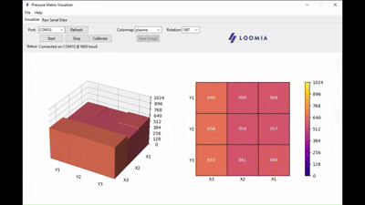
}Visualizer Schematic
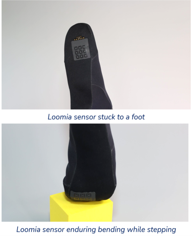
FSR Bend Radius and Integration
Validated Through Independent Lab Testing
Loomia FSRs have been evaluated in a university laboratory environment. The images above shown reflect bend radius testing.
Our sensors have a broad sensing range and reliable performance on both flat and gently curved surfaces.
Integration Instructions:
Our components are designed for easy integration onto surfaces. To attach our LEL to a surface (textile or plastic) Follow the instructions below:
Using the peel-and-stick backing, gently peel off the brown paper.
With adhesive exposed, apply the sticky component to your surface and ensure there are no bubbles.
Press down firmly
Do not lift or re-apply
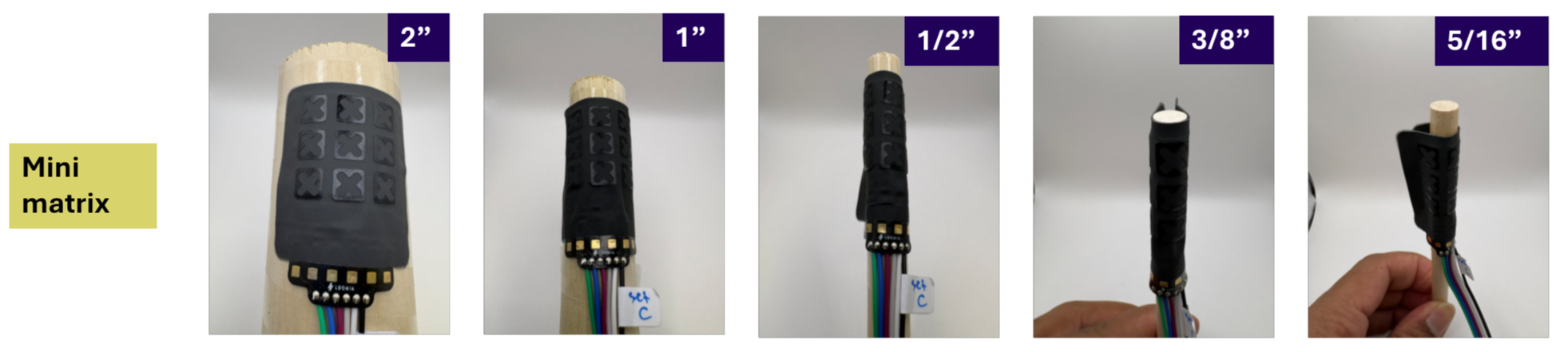
The Mini Matrix - FAQ
-
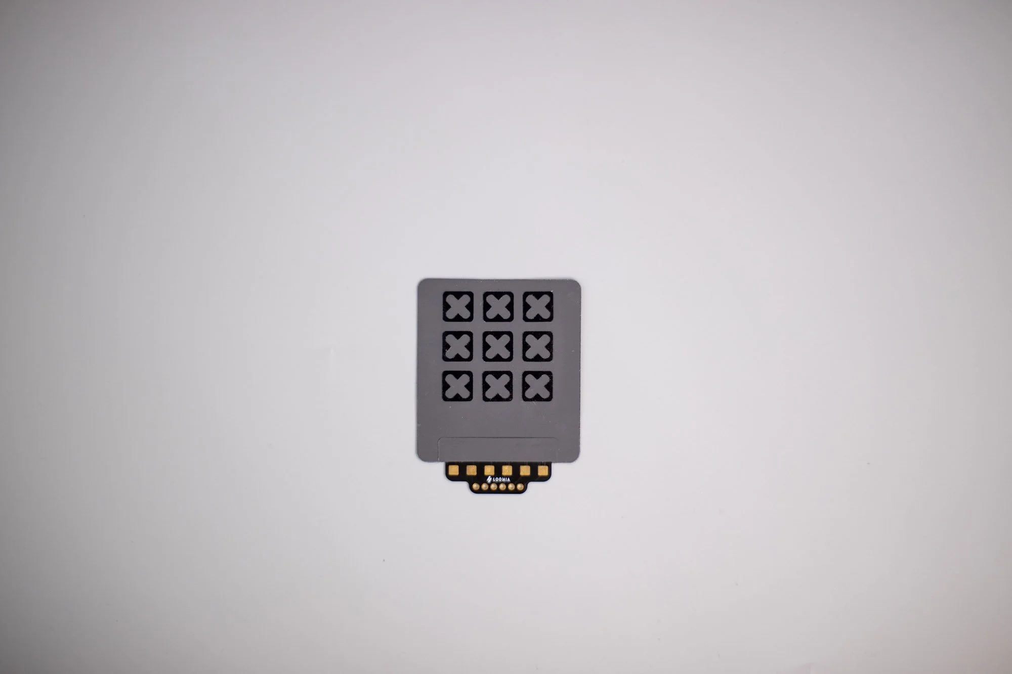
The Mini Matrix Force Sensitive Resistor (FSR) is a flexible 3×3 force-sensing matrix with 9 individual sensor cells. It provides an analog output that maps force distribution across the sensing area.
-
Each sensing cell measures 8.9 mm, and the overall component size is approximately 46 mm × 53 mm.
-
The Mini Matrix FSR operates by decreasing resistance as pressure increases. This allows the sensor to generate an analog readout that reflects applied force across the matrix.
-
The Mini Matrix FSR is best suited for flat or slightly curved surfaces and supports bending down to an 8 mm bend radius while maintaining reliable performance.
-
The Mini Matrix FSR supports a minimum force below 0.5 N and a recommended maximum operational force of 65 N. It features a thickness of 0.5 mm, a minimum feature size of 2.5 mm, and a breaking force above 100 N. Drift performance is 0.9% over one hour at 1 N and 13.3% over one hour at 50 N.
-
The Mini Matrix FSR supports visualization along with Arduino and Python scripts. It includes Arduino pinout documentation, a visualizer schematic, and peel-and-stick PSA backing for easy surface integration.